Part Configuration
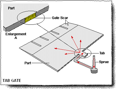
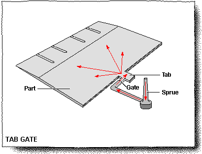
The arrows on the drawing represent the plastic flow from the sprue, runner, edge gate, tab, and into the part cavity. This method prevents jetting into the cavity or other surface imperfections. A stronger part will be obtained from the better flow pattern in the cavity and stress/strain is left in the tab.
Resin Filler
The tab gate has the same restrictions as the edge gate. Since an edge gate is located before the tab, there can be problems with low viscosity, long fiber, or some bead filled resins.

Gate Cosmetics
Enlargement “A” shows a large scar left from the tab that has been removed. The scar can be removed by snipping or by placing the part in a trim fixture. Since it is a rather large scar it is advisable to locate the tab on a non-cosmetic/non-functional area. Depending upon part design/function it may be possible to leave the tab.
Page 9 of 12

